Unibuilder Manual
Everything the plugin does, and the keys that do it. Covers Unibuilder 1.0 on Godot 4.7+.
Getting started
Installation
- Copy the
addons/unibuilder/folder from your purchase into your project'saddons/folder. - Open Project → Project Settings → Plugins and enable Unibuilder.
- The Unibuilder toolbar appears above the 3D viewport. You're ready.

Requirements: Godot 4.7 or later, any platform. The plugin is pure GDScript, so the standard Godot build runs it. You don't need .NET or any native libraries.
Upgrading from the demo. Close the project in Godot, then copy the full version's addons/unibuilder/ folder over the demo's. It is the same folder with the same files, so nothing else changes: the plugin stays enabled, your scenes open exactly as you left them, and every mesh keeps its materials, collision, and editable shape parameters. The demo's limits and watermark are gone the next time the project opens.
Your first mesh
- Open the Add menu on the toolbar and pick Cube.
- Press and drag in the viewport to draw the base rectangle on the grid, release, then move the mouse to pull out the height.
- Click to commit. The new object is selected and ready to edit, and drawing another shape chains straight on.
Press 4 to enter Face mode, click a face, then hold Shift and drag the move gizmo. That's an extrude, and it is the single gesture you will use most.
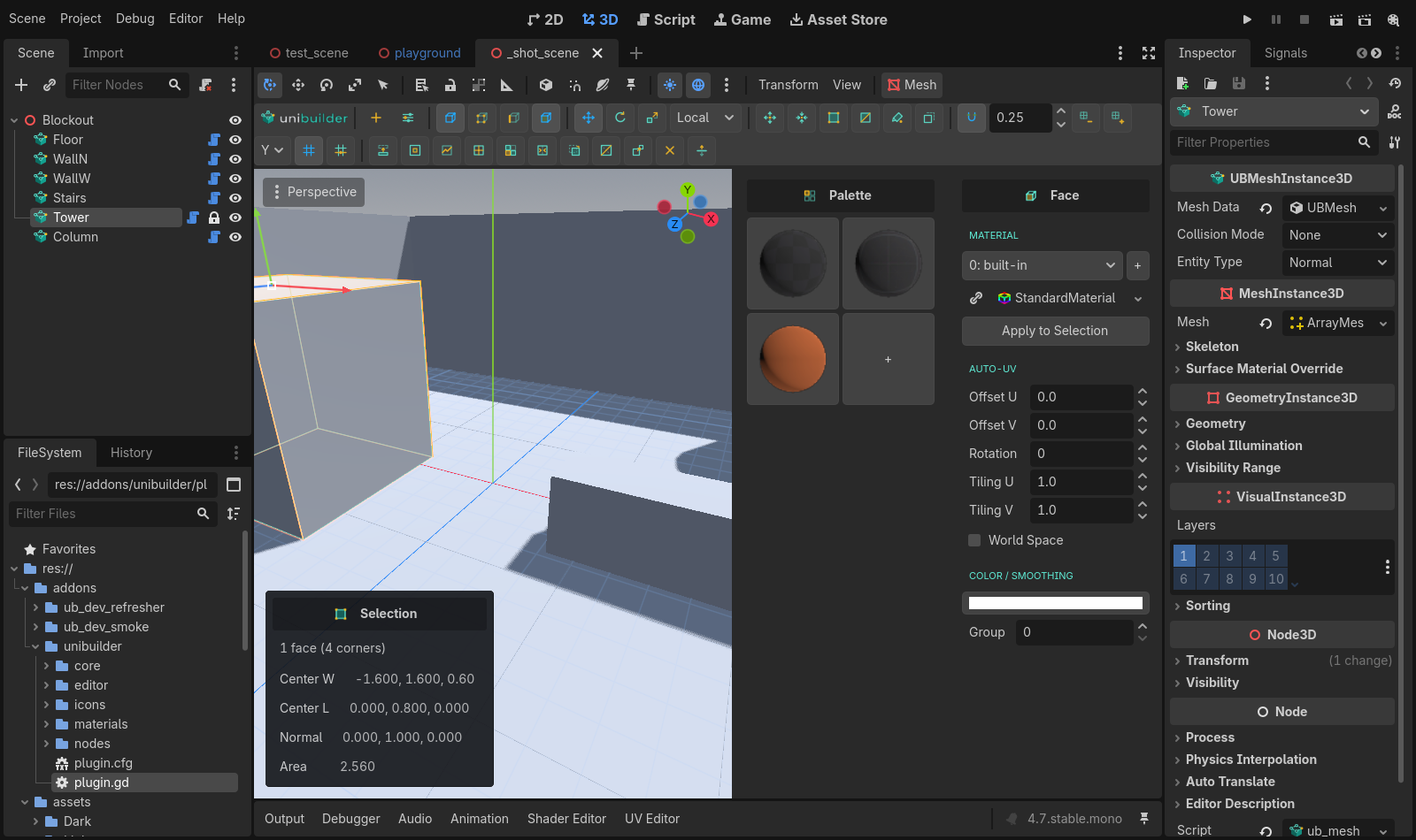
What a Unibuilder mesh is
Every Unibuilder object is a UBMeshInstance3D, which extends the ordinary MeshInstance3D. The editable model (n-gon faces, materials, UV settings, colors) lives in its mesh_data resource, and the plugin compiles it to a normal ArrayMesh whenever it changes. Because the compiled mesh is stored with the scene:
- the mesh renders, lightmaps, and occludes like any other mesh;
- scenes open and games run with the plugin disabled: the compiled mesh is saved in the scene, not rebuilt on load;
- exported games include collision, because the node script ships with the addon;
- duplicating a node (Ctrl+D, or copy and paste) gives the copy its own mesh data, so editing one never changes the other. The two share their materials, like any duplicated mesh does.
The grid and snapping
Unibuilder draws its own reference grid, independent of Godot's. One value drives both the visual density and the snap step, so what you see is what you snap to. The grid follows its toolbar toggle and nothing else; it doesn't wait for a mesh to be selected. Unibuilder saves the grid's state per project, never in your scenes.
Controls
| Control | What it does |
|---|---|
| Plane selector (X / Y / Z) | Which axis plane the grid lies on. Draw on walls by switching to X or Z. |
| Grid toggle | Show or hide the grid. Snapping still works with it hidden. |
| Step field, ÷2 / ×2 | The snap increment. Accepts values like 0.125. |
| [ / ] | Halve / double the step from the keyboard. |
| , / . | Nudge the grid plane along its axis by one step (for working at different floor heights). |
| Reset, 0 | Reset the plane offset to zero. |
| Snap toggle | Snap transforms to the grid. Hold Ctrl during a drag to temporarily invert it. |
| Align Grid | Moves the grid plane onto the current selection: coplanar with selected faces (the plane axis follows the face normal), or through selected vertices/edges on the current axis. With nothing selected, the plane goes through the object's origin. Saves nudging the plane by hand when you want to work off a surface that's already there. |
Absolute snap
Normal snapping moves a selection in whole grid steps from wherever it started, so a vertex that sits 0.3 off the grid stays 0.3 off it however far you drag. Turn on Absolute Snap in the Tools menu and a move lands the selection on the grid lines instead. Drag an axis arrow and only that axis snaps. Drag the center square and the selection lands on the nearest grid point. The selection still moves as one rigid block: its lowest corner is the point that lands on the grid, so a single vertex goes exactly onto a line and an edge or face keeps its size. It works the same way when you move a whole object. Along the grid plane's own axis the lines follow the plane's offset, so after Align Grid the selection lands on the grid you can see.
Per-element snap
By default a dragged selection snaps as one rigid block, keeping its shape. Turn on Per-Element Snap in the Tools menu and each vertex quantizes to the grid individually instead. The shape may distort; that's the point. Use it to conform loose geometry to the grid.
Vertex snapping
Hold V during any move drag. When the cursor comes near another vertex, an amber ring and crosshair mark it, and the dragged selection jumps so its grabbed vertex lands exactly on the target, with no gap between them.
- The anchor is the dragged vertex nearest your cursor when the drag started, so grab the gizmo near the corner you want to place.
- Targets include the rest of the current mesh and every vertex of every other Unibuilder mesh in the scene. Dragging a wall corner onto a floor corner is the intended use.
- In Object mode the whole node snaps by whichever of its vertices is nearest the cursor.
- Release V and the drag goes back to normal grid behavior.
Drawing shapes
Everything in the Add menu draws directly in the viewport and lands snapped to the grid, on the active grid plane. The button beside Add re-arms the last drawn shape in one click. It carries that shape's own icon, so it always shows what you'll get. The general gesture: press and drag the base, release, move to pull the height, click to commit. Esc cancels at any point, and pressing undo mid-draw cancels the draw too (it never rewinds scene history underneath a half-drawn shape). A dimensions label follows the cursor while you draw.
Every shape you draw stands on its base: its origin sits at the centre of its footprint on the plane you drew it on, and its geometry rises from there. That is what makes textures line up: a door and the wall beside it both measure their default texture from the floor, so they match vertically without switching to world-space texturing, and rotating or scaling a shape in Object mode works about the floor rather than the middle of the air. Center Pivot in the Tools menu moves the origin to the middle if you want it there.
While the tool is armed, the surface under your cursor highlights so you can tell exactly where a draw will land: a teal fill means that face lies on the current drawing plane (you're drawing on this floor); an amber outline means there's a surface there but the grid plane sits at a different height. Nudge the plane with , / . until it fills teal. With Snap on, the two grid lines under the cursor light up teal as well, brightest at the cursor and fading out along each arm, so you can see exactly which grid point a click or a drag corner will land on. They follow the snap lattice, so they also show up on a face you are drawing on with Draw on Surface, where no grid is drawn.
Or skip the plane bookkeeping entirely: the Draw on Surface toggle (next to the Grid button) makes armed shapes draw directly on the face under the cursor. The hovered face becomes the drawing plane, height pulls along its normal, and pointing at empty space falls back to the grid. Stacking a crate on a crate or putting a door frame on an upper floor stops needing grid-height nudging.
Plane, Sphere and Trim commit as soon as you release the base drag (they have no height pull).
Every shape remembers the settings you last used for it in this project, and the next one you draw starts from them: draw one turned staircase with a bullnose and the next staircase is turned and bullnosed too, at the same riser height. Only what the drag itself decides comes from the drag: the size, a staircase's step count (from the remembered riser height and the height you pull), a trim's height and which way it faces. The first staircase you draw gets one step per snap increment; every one after that reuses the last riser height you set (see Stairs in the table below).
The shapes
| Shape | Notes and parameters |
|---|---|
| Cube | The basic blockout unit. |
| Plane | Divisions U / V. |
| Cylinder / Cone | Sides, Smooth (round-shades the curved wall; the caps and base stay hard, so the rim keeps its edge). |
| Prism | Triangular wedge. |
| Stairs | Steps, Riser Height, Turn, Turn After, Flight Width, Landing, Open Risers, Stringer, Overhang, Lip, Bevel, Bevel Segs, Smooth. Solid and watertight. Settings that only matter once another is set stay out of the way until then: the landing fields appear when you pick a Turn, Stringer when Open Risers is on, Lip with an Overhang or open risers, and Bevel Segs and Smooth once there is a Bevel to round. The stairs rise in the direction you last dragged while drawing the base, so nudge the cursor toward where the top should be. Steps and Riser Height describe the same count from two sides: change either and the other follows. Because every setting carries over to the next staircase, a level shares one riser height without counting: each new flight takes as many steps of the remembered riser as its drawn height needs. Turn adds a landing: Left or Right sends the second flight across the rest of the footprint at a right angle, U Left or U Right sends it back beside the first flight with a well between them. Set Flight Width to half the drawn width and the two flights meet with no well. Turn After sets how many risers come before the landing (0 splits them evenly), Flight Width sizes the first flight and Landing sets its depth. Open Risers replaces the solid block with separate tread slabs, each as thick as the Lip, and Stringer adds a sloped beam of that width under each side of every flight. Overhang projects each tread past its riser with a lip of the given thickness underneath, keeping the overall footprint; Bevel cuts the front edge of every tread (and the lip's bottom edge when there is one), flat at one segment and rounded above that. Set Bevel to half the Lip for a full bullnose. Smooth shades the rounded parts as a curve. The ramp collision follows a turned staircase too: one smooth wedge per flight and a block for the landing. |
| Curved Stairs | Steps, Arc (degrees), Inner Radius. Stairs sweeping around an arc. |
| Wall | Thickness, Height, Side. A wall run along the corners you click, with mitred corners at any angle. Click the corners on the grid like a Poly Shape: the next segment follows the cursor as you go. Press Enter to finish an open run, or click the first corner again to close a room. Backspace removes the last corner, Esc cancels. Hold Shift while placing a corner to hold the segment to the nearest grid axis, for walls that run dead straight along X or Z; the same works for Poly Shape corners. Nothing is pulled: the wall is as high and thick as the last wall you made (2 by 0.2 to begin with) and you retype both in the adjust panel. Side puts the thickness centred on your line or wholly to its left or right, seen walking the corners in the order you clicked them. |
| Trim | Profile, Depth, Height, Arc Segs, On Wall, Flip Side, Upside Down, Smooth. A moulding strip against a wall: skirting, dado rail, cornice. One drag draws it: the base is its length by its height, it commits when you release, and it runs in the direction you ended the drag. Its depth is never dragged, since a trim is far thinner than any grid step: it starts at the last Depth you set in this project (5 cm before you set one) and you retype it in the adjust panel. On a floor the strip stands up on the edge you started the drag from, so start at the wall. With Draw on Surface pointed at a wall it lies flat on the wall, its bottom on the lower edge of the drag. Profiles: Flat, Chamfer, Round (a bullnose), Cove (a hollowed face), Ogee (an S curve) and Stepped (two boards). Every profile is drawn as a skirting; Upside Down turns it into its cornice twin. Depth and Height can be retyped for exact sizes the grid will not give you, and the strip keeps its corner against the wall when you do. Flip Side moves the back to the other edge of the drawn base; On Wall records which way the strip was drawn. |
| Trim Walls | Profile, Depth, Height, Arc Segs, Placement, Offset, Upside Down, Smooth. Trim swept along the walls you click, with mitred corners. Arm it and its parameters appear in the adjust panel straight away, so you can pick Placement (Bottom for a skirting, Top for a cornice), a profile and sizes while you choose the walls. Click wall faces, on any Unibuilder objects, in any order; a wall highlights teal when the cursor is over it and amber once chosen, and the trim previews as you go. Click a wall again to drop it, Backspace drops the last one, Enter, a double-click or the panel's Apply commits, Esc or Cancel abandons it. The strip sits where the wall meets the room: if your wall cubes reach down below the floor slab, the skirting still lands on the slab's surface, and a cornice tucks under the ceiling slab. Walls that meet at a corner join with a clean mitre at any angle, walls that overlap only carry trim on their visible run, and walls that run all the way round a room close into a ring. Only closed objects hide trim like this: an open mesh such as a plane or a sculpted terrain has no inside, so it never cuts a run short, though the strip still settles on it as a floor. A doorway cut through a wall breaks the run at the jambs. Placement puts the strip along the walls' bottom edge (a skirting) or hangs it from their top edge (a cornice), Offset slides it up or down, and the profiles are the same six as Trim. The result is one new object; its parameters stay live for the same walls. |
| Arch | Radius, arc segments, Smooth (round-shades the curved underside). |
| Door | A doorway frame: a lintel band over the opening and side posts. The span runs in the direction you last dragged while drawing the base, like stairs; a double-headed arrow shows the walk-through direction while you draw. Door Height and Doorway Width are in world units, whatever size you drew the frame: the first door is 2.1 high and 0.9 wide, and every door after that starts from the last one you set. Type the opening you need and the band above and the posts beside it follow. Arched swaps the flat lintel for an arc. Smooth round-shades the arc. |
| Sphere | Subdivs, Smooth (on by default; uncheck it for a faceted low-poly ball). Built from quads with no pole fans. |
| Torus | Tube Radius, Ring Segs, Tube Segs. Base drag sets the outer diameter, height pull sets the tube. |
| Pipe | Thickness, Sides. A tube with real inner walls. |
| Poly Shape | Click points to outline any polygon (Backspace removes the last point), close it by clicking the first point or pressing Enter, then pull the height and click. |
Every solid primitive is watertight, which matters later: booleans require it. Plane is the exception, because a flat open surface has no volume for a boolean to work on.
Editing parameters after committing
After you commit a parametric shape, its parameters appear in the adjust panel floating at the viewport's bottom-right and stay live: change the step count of stairs or the arc segments of an arch and watch it rebuild. The shape stays adjustable until you move on to something else, which commits it as one undo entry.
The panel also keeps presets: once you have a staircase or a trim the way you like it, press Save in the panel's top row, give it a name, and it is stored with the project for that shape (or that action, since bevel, inset and the rest have presets too). Pick a preset from the dropdown to apply it to whatever the panel is showing, including the Trim Walls panel before you confirm. Saving under an existing name replaces it; Delete removes the picked one. A preset never changes the things the drag decided, such as which way a trim faces.
You can come back to them later. Select the shape and press the parameters button on the toolbar (next to Add and the repeat-shape button) to reopen its controls, including in a later session, since the parameters are saved with the scene. The button is greyed out when the shape's parameters can no longer be used, which happens as soon as the mesh itself is edited: moving a vertex, extruding a face, painting a face, unwrapping it by hand, or freezing its transform all mean a rebuild would throw that work away, so Unibuilder stops offering it. Undo those edits and the parameters come back. Assigning a material is the exception: it carries across a rebuild, so texturing a shape doesn't cost you its parameters. (Per-face materials can't be mapped onto a different face count; if you've assigned several, a rebuild falls back to the first face's material and says so.)
Selection
Modes
1 Object, 2 Vertex, 3 Edge, 4 Face, 5 Paint, 6 Material. Esc returns to Object mode. The toolbar buttons mirror the keys.
Switching modes converts your selection instead of dropping it: a selected face becomes its four edges in Edge mode, its four vertices in Vertex mode, and going back up keeps only elements that are fully covered (two vertices of a quad are not enough to reselect the quad).
Picking
- Click selects, Shift+click adds or removes. As you move the mouse, the element a click would pick lights up.
- Drag in empty space for a marquee. The X-Ray toggle makes the marquee select through geometry instead of only what you can see.
- Picking works against Unibuilder's own data, so you never need collision shapes for editing.
Loops and rings
- Double-click an edge: edge loop. Alt+double-click: edge ring.
- Double-click a face: face loop, steered by the nearest edge under the cursor.
The selection info panel
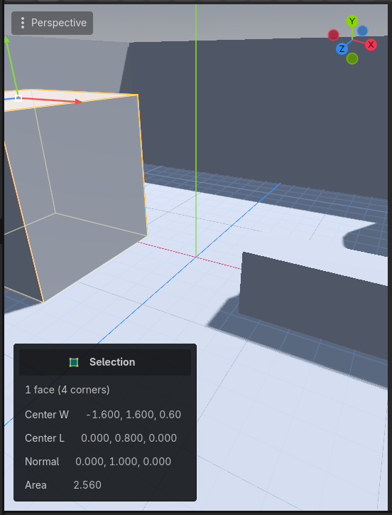
Whenever elements are selected, a translucent info panel floats over the viewport's bottom-left corner. It tells you what you have and where it is, in both world and local coordinates, and it costs no dock space. The values sit in read-only fields you can copy from.
- One vertex: editable world X/Y/Z (type exact coordinates; one undo entry per commit) plus the local position.
- One edge: length and midpoint. Several edges: count, total length, and the group's center and bounds.
- One face: corner count, center, world normal, and area. Several faces: count, total area, center, and bounds.
- Groups of vertices show their center (world and local) and bounding size.
If you'd rather read the size off the viewport itself, turn on Show Dimensions in the Tools menu. The selection's world-space size is drawn beside it, or the whole mesh's in Object mode. The setting sticks between sessions.
Selection tools
| Tool | What it does |
|---|---|
| Grow / Shrink | Expand the selection to adjacent elements, or contract it from its boundary. Face-mode Grow can be angle-limited in Preferences, so growth stops at hard corners. |
| Select All Ctrl+A | Every element of the current mode. |
| Invert Ctrl+I | Selected becomes unselected and vice versa. |
| Select Similar (Face mode) | Every face sharing material, smoothing group, and color with the selection. |
| Select Coplanar (Face mode) | Grows the selection over every neighbour lying flat in the same plane, stopping at the first bend. The quick way to grab a whole subdivided floor or wall before merging, texturing, or extruding it. Faces on the same plane elsewhere in the mesh are left alone, since the growth only ever crosses shared edges. |
| Select Holes (Edge mode) | Every boundary edge in the mesh. Works from an empty selection; run Fill Hole afterwards. |
Transforms
The gizmos
Shift+W Move, Shift+E Rotate, Shift+R Scale (plain W/E/R stay Godot's own tool keys). The same gizmos drive element selections and, when a Unibuilder node is the only thing selected, the whole object in Object mode, so object transforms snap to the same grid as everything else. Multi-object selections keep Godot's native gizmo.
- Move: axis arrows plus a view-plane center square.
- Rotate: three axis circles with a live degree readout. Snapping is 15° steps; drags past 180° keep counting.
- Scale: axis handles plus a uniform center. The readout shows the live factor, and snapping quantizes factors to the grid step (×0.5, ×1.25 and so on).
- Esc cancels any drag in progress. Ctrl inverts snapping while dragging.
Orientation
The toolbar dropdown switches gizmo orientation between Global (world axes), Local (the node's basis), and Normal (the blue axis points out of the selected faces). Normal is the one to use for pushing a slanted face straight out along its own direction.
Proportional editing
The falloff menu beside the orientation dropdown turns proportional editing on and picks its falloff. The button wears the icon of whatever you picked, dimmed while off; choose Off to turn it off. While a falloff is active, move, rotate, and scale drags also pull the unselected vertices near the selection: full strength at the selection, fading to nothing at the edge of the radius. Dragging one vertex up out of a flat plane makes a hill instead of a spike.
- The falloff sets the shape of the pull, and each menu entry's icon draws its curve. Smooth eases in and out and suits most work. Sphere holds close to full strength across the radius and rounds off at the rim; Root and Inverse Square sit between Sphere and Linear. Linear fades evenly with distance. Sharp concentrates the pull close to the selection. Constant moves everything inside the radius at full strength, with a hard edge at the rim.
- The number field beside the menu sets the radius in world units.
- During a drag, a teal circle marks the radius. Roll the mouse wheel to grow or shrink it without letting go, and the mesh reshapes as you scroll.
- Grid snapping still applies to the vertices you selected. The soft neighbours stay off the grid on purpose, because snapping a partial offset would break the falloff. Per-element snap follows the same rule: it lands the selected vertices on the grid and leaves the rest free.
- The falloff measures straight-line distance, not distance along the surface, so it reaches through geometry: a vertex on the far side of a thin wall can sit inside the radius. Shrink the radius when that matters.
- The texture survives the sculpt. Faces the drag tilts keep the flat plane's mapping, so a texture runs over the hill unbroken instead of jumping at every edge. See Auto-UV settings.
Shift-drag extrude
In Face mode with the Move gizmo, hold Shift and drag: the selection extrudes and the new geometry follows the drag. This is the fastest way to rough out volumes.
Shift-drag inset
The same gesture on the Scale gizmo insets instead. In Face mode, hold Shift and drag a handle: the width appears at the cursor and the faces inset live. Drag an axis handle toward the pivot to inset (dragging away does nothing, since there is no negative inset); from the center square, drag in any direction and the distance you travel is the width. Hold Alt for the equal-width mode, which you can toggle mid-drag. With Snap on, the width lands on grid steps, and Ctrl inverts that as usual.
Releasing the mouse leaves the inset open in the adjust panel, so you can type an exact width or flip Equal after the fact; it commits like any other operation when you move on.
Pivot tools
| Tool ( Tools menu) | What it does |
|---|---|
| Center Pivot | Moves the node origin to the center of the mesh bounds. The mesh does not move in the world. |
| Set Pivot to Selection | Moves the origin to the current element selection, e.g. a door's hinge corner. |
| Freeze Transform | Bakes the node's transform into the vertices and resets it to identity. The mesh stays exactly where it is. |
Editing operations
The toolbar shows the operations valid for the current mode. Anything with parameters opens in the adjust panel after it runs.
The adjust panel
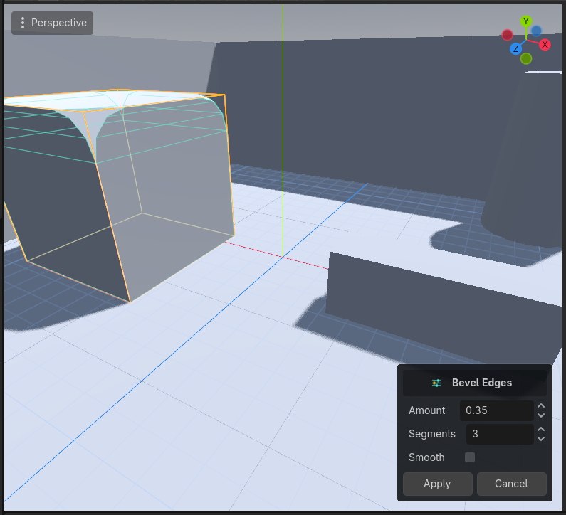
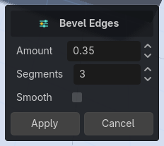
After a parameterised operation runs, its parameters appear in a translucent panel floating at the viewport's bottom-right (the Selection panel's twin on the other corner) and edit live: the mesh re-applies the operation as you change values. Click Apply, run something else, or change the selection and the result commits as one undo entry. Esc in the viewport or Cancel reverts it entirely.
Ctrl+Z while the panel is still up closes the session and undoes the operation, as you would expect, and Ctrl+Shift+Z brings it back. The exception is a gesture still in progress (a gizmo drag, or a Ctrl+B modal drag before you have clicked): there the chord cancels the gesture, exactly like Esc.
There is also a modal version: select edges and press Ctrl+B to drive a bevel's width with the mouse (the wheel changes segment count); in Face mode the same key drives Inset. Click commits, Esc cancels. The panel stays live throughout and its fields follow the mouse, so you can drag to roughly the right value, let go, and type the exact one.
Vertex mode
| Op | What it does |
|---|---|
| Weld | Merges vertices closer than a threshold (adjustable afterwards). |
| Collapse | Merges the selected vertices to their center. |
| Split | Un-shares a vertex so each face gets its own copy. |
| Connect | Inserts edges between selected vertices on a shared face. Three or more vertices on one face carve it repeatedly. |
| Fill | Select the rim vertices of a hole and it closes. |
With exactly one vertex selected, the selection info panel turns its world X/Y/Z into editable fields, so you can type exact coordinates instead of dragging.
Edge mode
| Op | What it does |
|---|---|
| Extrude | Pulls new geometry out of boundary edges, in the surface plane. |
| Bridge | Connects two open edges with a face. Both edges must sit on a boundary; it understands crossings and fills openings with the correct winding. |
| Bevel | Chamfers edges. The Segments parameter (1 to 8) rounds the chamfer into an arc; Smooth gives the new faces their own smoothing group. Works on interior and boundary edges. |
| Connect | Splits faces that have exactly two selected edges through their midpoints, a partial loop insert. |
| Insert Loop | Inserts a loop along the ring of the selected edge. The Cuts parameter spaces several evenly. |
| Subdivide | Splits selected edges into N equal segments. |
| Fill Hole | Select any edge of a hole's rim and it closes. |
| Insert Vertex | A click tool: click along any edge to splice a vertex at that spot, snapped along the edge. Esc ends it. |
Face mode
| Op | What it does |
|---|---|
| Extrude | Pushes faces out along the group normal, building side walls. Shift-drag the gizmo for the freeform version. |
| Inset | Shrinks a copy of each face inward, ready to extrude. The Equal toggle keeps the rim width uniform on non-square faces. |
| Subdivide | Splits faces into a grid; the Segments parameter controls density. Painted vertex colors carry across, interpolated smoothly over the new grid. |
| Merge | Joins selected faces into one n-gon. It refuses regions with holes or bow-ties rather than making bad geometry. |
| Detach | Moves the selected faces into a new object, then switches you to that object with all of its faces selected, ready to move or extrude. |
| Duplicate | Copies faces in place and selects the copies, ready to drag away. |
| Delete Del | Removes faces, leaving a hole. |
| Flip | Reverses the winding, turning a face inside out. |
| Flip Face Edge | Rotates the internal diagonal of a non-planar quad, changing how it bends. |
The Cut tool
Cut draws a new sub-face directly onto an existing face. Activate it, click a face, click your points, and close via the first point or Enter (Backspace removes the last one). The face re-triangulates cleanly around your polygon, concave faces included, and the new sub-face is selected, ready for an extrude or inset. Cutting a doorway into a wall is the canonical use.
With Snap on, a cut point prefers the target face's own vertices and edges: come within a few pixels of one and the cursor marker turns amber, and the point lands exactly on it. Otherwise it snaps to a grid at the snap step, laid out in the face's own plane. Putting points on the outer boundary is how you cut a face clean in two instead of carving an island inside it. Ctrl inverts the toggle, same as anywhere else.
Materials and face properties
Materials
In Face mode, the panel on the right edge manages material slots. Pick or create a slot, then Apply assigns it to the selected faces. One mesh can carry any number of materials, and Unibuilder builds one mesh surface for each slot you use.
Faster: drag a material from the FileSystem dock straight onto the mesh in the viewport. In Face mode it lands on the face under the cursor, or on the whole selection if that face is part of it. Object, Vertex, and Edge mode have no face selection to aim at, so a drop there covers the entire mesh. Switch to Face mode first if that isn't what you want.
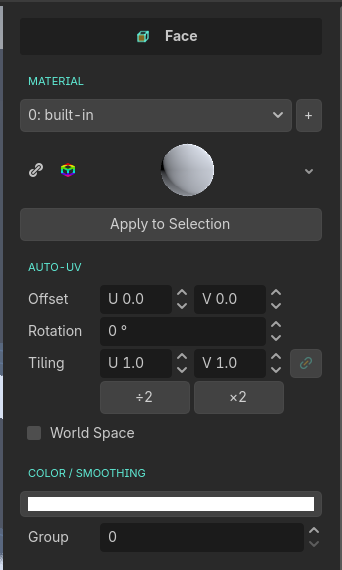
The material palette
The Palette is a per-project library of your go-to materials. It appears in the right dock whenever you're editing a Unibuilder mesh: under the face panel in Face mode, on its own in every other mode. Click a swatch and it applies to the selected faces; with no face selection (including Object mode) it applies to the whole mesh. Either way it's a single undo step. Drag any material in (from the FileSystem dock, an inspector slot, or with the small + button) to pin it; pinned swatches persist with the project. Swatches also drag back out onto faces, exactly like dragging from the FileSystem dock.
- The last couple of materials you applied by any means appear as dimmed recent swatches automatically; right-click one to pin it for good.
- Right-click a pinned swatch to remove it. If a pinned material's file goes missing, the swatch shows ! with the old path in its tooltip instead of silently disappearing.
- The palette is a project library; the slot list above it belongs to the edited mesh. Removing from one never touches the other.
- Default for new shapes: right-click a swatch → Set as Default. A small corner badge appears ( a teal cog with an amber check mark), and every shape you draw from then on comes out wearing that material, including the live preview and any post-commit parameter tweaks. Right-click again to clear it.
Auto-UV settings
Every face starts with automatic planar UVs. The dominant axis picks which way the texture runs, but the projection lands on the face's own plane, so texel density is the same on a sloped face as on a flat one. A checker stays square on a chamfer, a cone side or a cylinder wall. The face panel adjusts the mapping live per face: offset U/V, rotation, tiling U/V, and a world-space anchor toggle. The ÷2 and ×2 buttons under the tiling pair halve or double both axes at once, which is the power-of-two step texturing usually wants. The link toggle beside the tiling fields keeps U and V equal: edit either one and both change.
- Local (default): the texture follows the face as the object moves.
- World: the texture stays put in world space while the face slides through it. Handy for continuous brick or tile across separate objects.
Automatic UVs are per-face, so the texture still changes direction where two faces meet at an angle. That is what a box-mapped cube always did at its corners. Bending geometry out of shape is the exception. When a move drag tilts a face by pulling only some of its corners, the face keeps projecting the way it did before the drag instead of switching to its new slope. Sculpt a flat plane into hills with proportional editing and the whole surface keeps its top-down mapping, so the texture runs over the hills without a break; the slopes stretch it a little, which is what a top-down map on a slope always does. A face moved or turned as a whole still re-projects on its new plane, and a face dragged back flat goes back to projecting from its own slope. Press Auto in the UV editor to make a face project from its current slope again. Curved shapes avoid it by arriving pre-unwrapped: cylinders, cones, spheres, toruses and pipes are drawn with continuous UVs already baked onto their curved faces, so a texture runs around the curve unbroken with a single seam per loop. Cylinder, cone and pipe walls unroll flat at exact 1:1 density; spheres use the familiar equirectangular map, with its usual pinch at the poles. Flat caps and bases keep the automatic mapping, which already lines up across them. Beveling works the same way: a bevel bakes UVs onto the band it creates so the texture carries around the corner unbroken from one of the two faces, at the right scale, however many segments the bevel has. Baked faces are manual faces (bright in the UV editor). Edit them there, or press Auto to return them to the automatic per-face mapping. One thing to know: the face panel's offset, rotation and tiling fields drive the automatic mapping only, so on a baked curved wall adjust the texture in the UV editor instead.
Smoothing groups
Each face carries a smoothing group number. Faces in the same group shade smoothly across their shared edges; group 0 means hard. The number field for it is in the face panel. Curved primitives (spheres, cylinder walls, smooth arches) set theirs automatically.
The UV editor
Open the UV Editor bottom panel with a Unibuilder mesh selected. It shows the UV layout of your 3D face selection, or the whole mesh when nothing is selected, over the material's texture. Auto faces draw dimmed; manual faces draw bright. Manual faces behave sensibly when you move geometry afterwards: move or turn a whole face and its texture travels with it, but pull only some of its corners (lifting a cylinder's cap, say) and the texture keeps its size and pattern instead of stretching, just as an auto face would. While your cursor is over the panel, the amber face tint in the 3D viewport hides itself so you can watch the texture move on the mesh as you edit.
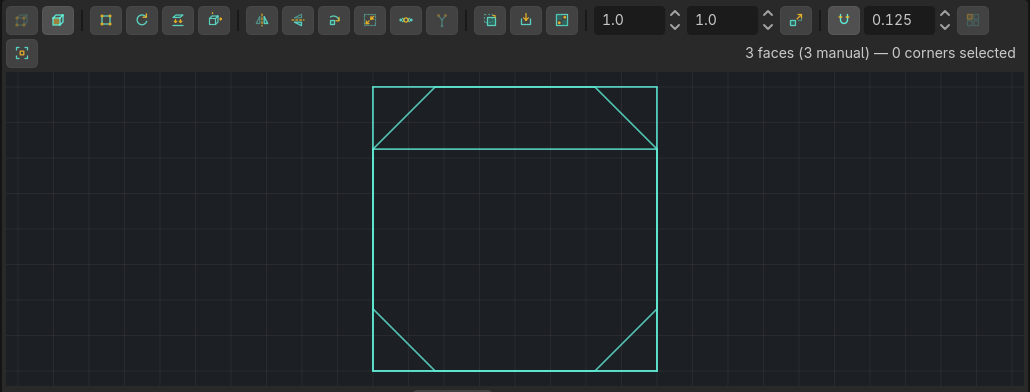
Navigation and selection
| Input | What it does |
|---|---|
| Middle-drag / wheel | Pan / zoom (cursor-anchored). Frame recenters on the 0 to 1 square, and Frame Selection zooms to whatever you have picked, leaving a margin around it. With nothing picked in the editor it frames every face on display. |
| Verts / Faces toggles | Whether clicks pick UV corners or whole UV faces. |
| Click, Shift+click, drag | Select, toggle, marquee. A vertex click grabs every corner stacked at that point. |
| Double-click | Selects the whole UV island. Shift adds another island. |
| Tile toggle | Repeats the texture across the view; the 0 to 1 square stays outlined. |
Moving, scaling, rotating
- Drag moves the selection, snapped to the UV grid step. Editing an auto face quietly bakes it to manual first, so nothing visibly jumps.
- Ctrl+drag scales about the selection center, with a live ×factor readout. Shift while dragging switches to per-axis.
- Alt+drag rotates about the selection center with a degree readout, in 15° detents when Snap is on.
Tools
| Button | What it does |
|---|---|
| Manual / Auto | Bake the current projection into editable per-corner UVs, or return faces to automatic projection. |
| Planar / Box | Project the faces as one island along their average normal, or per-face along dominant axes. |
| Flip U / Flip V / Rot 90 / Fit | Mirror, quarter-turn, or fit the selection into the 0 to 1 square. |
| Sew | Welds selected corners that share a 3D vertex, stitching islands together. |
| Split | A picking toggle: vertex clicks grab one corner instead of the whole stack, so dragging tears a seam open. |
| Copy / Paste | Copies the first selected face's layout and pastes it onto faces with the same corner count. |
| Texel | Rescales every island touching the selection so texture density matches the first selected face. Check it with a checker texture: the squares end up the same size everywhere. |
Material mode
Material mode lines a texture up on a face without leaving the 3D view. Press 6 or click the Material button in the toolbar's mode switcher. Your selection converts to faces on the way in, the amber face highlight switches off so you can see the texture you are adjusting, and a gizmo appears on the selected face. Click a face to select it, Shift+click to add or remove one, and click empty space to clear. Grow, Shrink, Select All and Invert still work here. Press 6 again, Esc, or any other mode to leave.
The gizmo is built from the face's own texture mapping, so its two axes point the way the texture actually runs across the surface: teal is U, amber is V. Drag the centre square to slide the texture, drag the square at the end of either axis to stretch it along that axis, drag the small square between the two tips to scale it evenly, and drag the ring to turn it. The texture follows the cursor in every case: the spot you grabbed stays under the pointer as you move.
With Snap on, sliding snaps to the UV editor's grid step, turning snaps to 15 degree steps, and scaling snaps to that same step as a factor. Hold Ctrl to invert that while dragging. Each drag is one undo step. A face still on automatic mapping switches to manual mapping as part of the drag, exactly as it would in the UV editor, so the face panel's offset, rotation and tiling fields no longer apply to it afterwards; the UV editor's Auto button puts it back. With several faces selected, the gizmo sits on the largest one and every selected face moves together about the group's shared centre.
Vertex painting
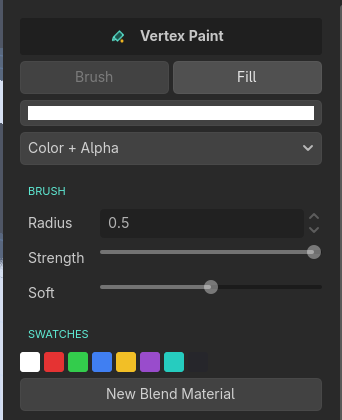
Paint is a mode like the selection modes: press 5 or click the Paint button in the toolbar's mode switcher to enter it, and a palette panel docks on the right. Press 5 again, Esc, or any other mode to leave. The mesh stores vertex colors, so they survive baking. They also survive editing: subdivide, merge, connect, insert loop, cut, and bevel all carry the paint across, spreading it over whatever geometry they create.
The brush
- The panel's Brush setting is a real brush: a sphere reticle sits on the surface under the cursor, and press-drag blends color in with radius, strength, and falloff from the panel.
- Holding still doesn't compound: one stroke applies at most one full dab anywhere.
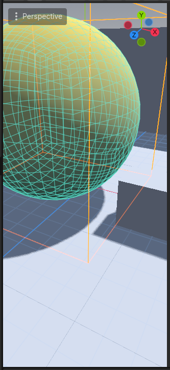
- Fill hard-fills whole faces per click. The mesh shows its wireframe and the face under the cursor lights up so you can see exactly what a click will color. Use it for color-coding blockouts.
- Shift+click eyedrops the color under the cursor. One stroke is one undo entry. Esc cancels a live stroke, then exits paint.
- Swatches: click applies, Ctrl+click (Cmd on Mac) stores the current color. They persist between sessions.
The two-texture blend workflow
The panel's channel mode separates color from alpha so they never fight: Color+Alpha, Color only, or Alpha only. New Blend Material assigns a material that blends two complete material layers by painted alpha, and tints by painted color. Set the mode to Alpha only, fill in the two layers, and paint dirt, moss, or wear exactly where you want it. If the mask came out the wrong way round, Invert Alpha flips the painted alpha of the selected faces (the whole mesh with no face selection) so the two layers swap places without a repaint. Color is left alone, and one undo puts it back. The material has its own Invert Mask checkbox in its Blend group, which swaps the layers for every face using that material without changing the paint at all. Use the panel button when the mask on some faces is wrong, and the material checkbox when the whole material simply has its layers the wrong way round.
You can also create one by hand anywhere a material goes: in any material slot, open the resource dropdown and pick UBBlendMaterial from the New list, alongside StandardMaterial3D.
Filling in two layers by hand is a lot of clicking, so Tools ▸ Blend Layer A from Material… (and the Layer B twin) copies an existing material into one layer in a single step. Point it at any StandardMaterial3D or ORMMaterial3D and it brings across albedo, normal, roughness, metallic, ambient occlusion, height, emission, and the UV tiling. An ORM texture is wired into all three of its channels automatically. Maps the source has switched off stay off, so what you get looks like what the source looked like. It fills the blend material on the selected faces, or the mesh's own if nothing is selected, and it's one undo step.
Blend materials get their own swatch preview in the material palette: a sphere with noisy vertex alpha, so you can see both layers and the transition between them at a glance. Godot's own material preview (the sphere in the inspector, and the thumbnail in the FileSystem dock) can't show this, because its preview mesh has no vertex colours to blend by, so it shows layer B only. The palette swatch is the one to trust.
Each layer (Layer A, Layer B in the inspector) takes the same maps a standard material does (albedo, normal, roughness, metallic, ambient occlusion, emission) plus its own UV tiling and offset, so the two halves can use different texture scales. Every map is optional: an empty slot falls back to that layer's slider. The roughness, metallic, and AO slots each pick a color channel, so one ORM texture feeds all three (AO = Red, Roughness = Green, Metallic = Blue).
Under Blend, Height Blend changes what the paint means. At 0 the layers cross-fade evenly. Raise it with height maps assigned and the layers interlock by their own relief instead, so gravel pokes through mud and mortar shows between bricks. Blend Sharpness sets how wide the transition band is; small values give a hard, rocky edge. If one layer's height map runs brighter than the other's and drowns it out, each layer has a Height Offset to level the contest: raise the quiet layer or lower the loud one until a 50/50 paint reads as 50/50.
The same height maps can carve apparent depth into the surface: enable Deep Parallax (in the material's Parallax group) and the view sinks into the blended relief exactly like the standard material's mode of the same name, with the same Scale and Min/Max Layers settings. It follows whichever layer is showing: paint gravel over mud and you look down into the gravel, not the mud. Off by default; it costs a texture-march per pixel, so treat it as a hero-surface effect rather than a blockout default.
Booleans
Tools menu: Boolean Union / Subtract / Intersect. Select mesh A, then add mesh B to the selection so both are selected, and run the operation. B is consumed, A becomes the result, and the result is ordinary editable geometry. One undo restores both.
Both meshes must be watertight (every edge shared by exactly two faces). If the edited mesh isn't, the operation refuses and selects the offending edges for you, switched into Edge mode. Usually a Fill Hole or Conform Normals fixes it, then run the boolean again.
- Materials survive: result surfaces keep the operand they came from.
- An intersect of two meshes that don't overlap warns and changes nothing.
- Marked experimental: the underlying kernel (Godot's Manifold CSG) is solid, but re-building clean editable n-gons from its output is best-effort on complex results.
Object tools
Whole-object operations (Tools menu)
| Tool | What it does |
|---|---|
| Merge Objects | Every other selected Unibuilder node merges into the edited one, transforms baked, materials preserved. One undo restores all the original nodes. |
| Mirror X / Y / Z | Duplicates the mesh reflected across the node's local axis plane and welds the seam. Model half a thing, delete the faces on the mirror plane, mirror, done: the result is watertight. |
| Triangulate Object | Converts every face to triangles. |
| Subdivide Object | Splits every face into a fan of quads around its center: four from a quad, one per corner from anything else. |
| Conform Normals | Fixes inside-out faces by flooding a consistent winding across the mesh, majority wins. |
| Convert to Unibuilder | Turns any selected plain triangle mesh (imports, CSG bakes) into an editable Unibuilder mesh: welds vertices, merges coplanar regions back into n-gons, and reconstructs smoothing from face angles. |
Collision
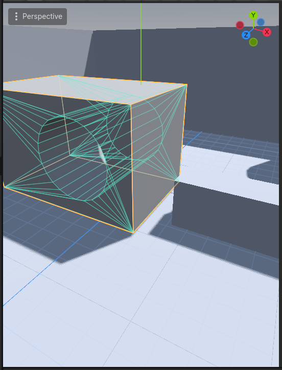
The collision_mode property on the node maintains an automatic collision body that regenerates on every edit and exists in exported games:
| Mode | Use for |
|---|---|
| Convex | Simple solid props. Fastest at runtime. |
| Trimesh | Exact static level geometry, including concave shapes. |
| Ramp | Stairs. A smooth wedge over the bounds so characters glide up instead of bumping each tread. |
The body is a child node named _UBCollision. It isn't stored in your scene file. The node rebuilds it from the mesh every time the scene loads, so it always matches the geometry and never goes stale. Baking is the exception: a baked mesh has no Unibuilder script left to rebuild anything, so the bake writes a real collision body into the scene.
Collider and Trigger volumes
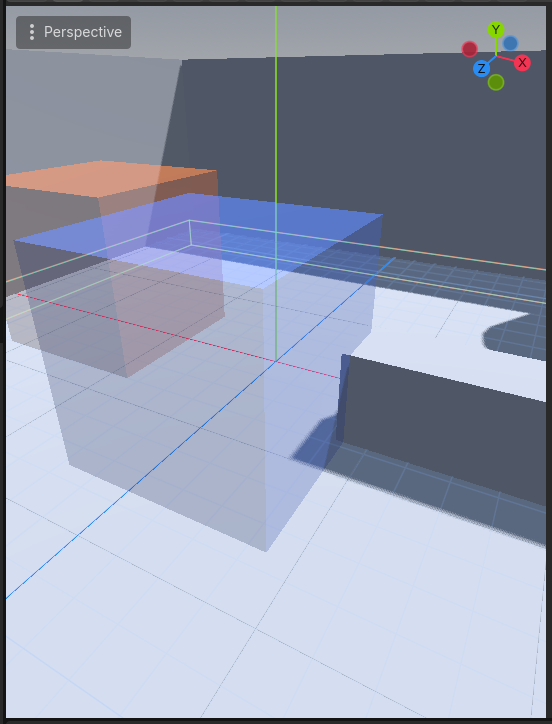
Set Collider and Set Trigger in the Tools menu mark a mesh as invisible helper geometry: tinted in the editor (orange for colliders, blue for triggers), hidden when the game runs, with the physics child left behind. A Collider keeps a StaticBody3D for invisible walls; a Trigger swaps it for an Area3D ready to fire body_entered. Running the same item again returns the mesh to normal.
Baking and exporting
| Tool | What it does |
|---|---|
| Bake to MeshInstance3D | Replaces the node with a plain MeshInstance3D carrying the compiled mesh, with lightmap UV2s generated so LightmapGI works out of the box. The texel size lives in Preferences; 0 skips it. Collision comes along: if the mesh had a collision mode set, the baked node keeps a real collision body as a saved child. Collider and trigger meshes bake invisible, the way they already behave when the game runs. |
| Export OBJ… | Writes an OBJ with n-gons preserved plus an MTL sidecar with base colors and texture references. Blender opens it correctly oriented. |
| Export glTF… | Writes .glb or .gltf of the compiled mesh with materials. |
You don't have to bake to get lightmaps. Live Unibuilder meshes generate their own UV2s too, so LightmapGI works on them as they are; the unwrap waits until a moment after you stop editing, so it never slows a drag down. The Live lightmap UV2 preference turns it off. Bake when you want to ship the geometry without the editing data attached.
Preferences
Tools ▸ Preferences: overlay colors, vertex handle size, the face-mode Grow angle limit (180 disables it), the lightmap texel size, and Live lightmap UV2 (on by default), which generates UV2s on live meshes as well as baked ones. Turn that one off if you never light your blockout. Settings persist per project.
Keyboard reference
| Key | Action |
|---|---|
| 1 2 3 4 5 6 | Object / Vertex / Edge / Face / Paint / Material mode |
| Esc | Back to Object mode; cancels any drag, modal tool, or adjust session first |
| Shift+W / E / R | Move / Rotate / Scale gizmo (plain W/E/R remain Godot's tool keys) |
| Shift+drag (Face mode, Move) | Extrude the selected faces |
| Shift+drag (Face mode, Scale) | Inset the selected faces (Alt for equal width) |
| V (hold, while move-dragging) | Vertex snapping |
| Mouse wheel (proportional drag) | Grow / shrink the falloff radius |
| Ctrl (hold, while dragging) | Invert grid snapping |
| Ctrl+A / Ctrl+I | Select all / invert selection |
| Ctrl+Z (adjust panel open) | Undoes the live operation; cancels a gesture still in progress |
| Double-click edge / Alt+double-click | Edge loop / edge ring |
| Double-click face | Face loop |
| Del (Face mode) | Delete faces |
| Ctrl+B | Modal bevel (Edge mode) / inset (Face mode) drag |
| [ / ] | Halve / double the grid step |
| , / . / 0 | Nudge grid plane down / up / reset |
| Backspace (Poly Shape / Cut) | Remove the last placed point |
| Enter (Poly Shape / Cut) | Close the outline |
| Shift+click (Paint) | Eyedrop |
| UV editor: Ctrl+drag / Alt+drag | Scale / rotate the UV selection |
| UV editor: double-click | Select UV island |
Performance and limits
- Editing cost scales linearly with face count. Typical blockout objects (up to roughly 1,000 faces) edit at full interactivity; at 5,000+ faces drags update at a few frames per second. Split very large levels across several objects, which you'd want anyway for undo granularity and occlusion.
- Paint strokes never trigger a recompile, so painting stays fast even on dense meshes.
- Unibuilder recompiles the whole mesh on every change. That is deliberate: it keeps every operation correct and every undo exact.
- The benchmark script that produced the published numbers ships in the repository; methodology is in the README.
Scene file size and load time
A Unibuilder mesh saves both its editable data and its compiled mesh into the scene, so scenes with a lot of geometry in them get large. It costs roughly 450 bytes per face, a little under two thirds of which is the editing data. That's fine at blockout scale (fifty cubes is about 160 KB), and it grows in a straight line from there: a single very dense 5,000-face mesh is around 2.3 MB on its own and adds about a fifth of a second to opening the scene.
Two things help, and both are worth doing on a large project:
- Save scenes in Godot's binary format (
.scninstead of.tscn). About 35% smaller and roughly three times faster to load, with no change to how you work. Text scenes are the friendlier choice for version control on small scenes, but once a scene holds thousands of faces its diffs stop being readable anyway. - Bake meshes you've finished editing. Dropping the editing data more than halves the file, and a baked mesh in a binary scene loads essentially instantly. On the 5,000-face mesh above that is 0.6 ms against 70 ms. Bake as a shipping step once a piece of geometry has stopped changing.
Troubleshooting
| Symptom | Likely cause and fix |
|---|---|
| A face looks like a hole from one side | It's inside out. Select it and Flip, or run Conform Normals on the object. |
| Boolean refuses to run | A mesh isn't watertight. The offending edges are already selected; Fill Hole usually fixes it. |
| Painted color doesn't show | The material needs Vertex Color → Use As Albedo, or use the blend material. |
| Texture crawls when the object moves | Those faces are world-anchored. Switch the anchor back to local in the face panel. |
| UVs went back to automatic after editing | A topology op changed the face's corner count, so stale manual UVs fell back. Re-bake with Manual. |
| The editor gizmo is gone in Object mode | A Unibuilder node was the sole selection, so Unibuilder's gizmo (grid-snapped) replaced it. Select multiple nodes to get the native one back. |
Found a bug? Report it on the issue tracker. Include your Godot version, what you did, and what you expected. If you can attach a small scene that shows the problem, the fix arrives faster.
License, in short
Per-seat: one license per person using the plugin in the editor, on as many of their machines as they like. You can use it on as many projects as you like, commercial ones included, and you owe no royalties. Games you ship may embed the plugin's runtime files. You may not redistribute the plugin itself, publicly or privately, modified or not. The full EULA ships with your purchase and is the binding text.